Torbjörn Rathsman
Anja is a sampler designed for live sound effect playback. Anja makes it possible to assign sound effects to the keys of the computer keyboard. Anja also features a channel mixer with 16 channels making it possible to fade a group of sound effects together, as well as MIDI capabilities for remote control. The backend of Anja is JACK, the low-latency audio server.
Anja would not have been possible without these people:
The author, 2017
Anja is free software: you can redistribute it and/or modify it under the terms of the GNU General Public License as published by the Free Software Foundation, either version 3 of the License, or (at your option) any later version.
Anja is distributed in the hope that it will be useful, but WITHOUT ANY WARRANTY; without even the implied warranty of MERCHANTABILITY or FITNESS FOR A PARTICULAR PURPOSE. See the GNU General Public License for more details.
You should have received a copy of the GNU General Public License along with this program. If not, see https://www.gnu.org/licenses/
The following table shows examples of notations used within this manual, or within Anja itself.
| Symbol | Meaning |
 | The surrounding box may contain useful tips or shortcuts |
 | The surrounding box contains information that will save you trouble |
 | You have done something in an incorrect way. The surrounding box contains information about how you should fix it. |
 | The desired action failed. The surrounding box contains information about what went wrong. |
| Key | A key on the computer keyboard |
| A button in the user interface | |
| An input field within the user interface | |
# (U+0023) | A symbol with its Unicode® codepoint in hexadecimal notation |
Anja is a sample player designed for live sound effect playback. Anja makes it possible to assign sound effects to the keys typing keys of the computer keyboard. To make it easier to find sound effects, each sound effect can have a description and a color, that shows up on Anja's virtual computer keyboard.
Anja also features a channel mixer with 16 channels. All sound effects are routed through one of these channels. The channel mixer makes it possible to fade a group of sound effects together. As with sound effects, each channel has a color and a description. In addition to color, description and channel gain, each channel also has an adjustable fade time, that is used to automatically fade the channel.
The backend of Anja is JACK, the low-latency audio server [1]. This makes it possible to connect Anja to other JACK clients enabling the creation of more complex signal flows.
The session file format of Anja described in more detail in Appendix G is in a formalized text format, optimized for human readability. The syntax of the session files has taken inspiration from formats such as Markdown [2] and is very similar to the syntax used in the “Doom template file” [3]. Therefore, session files can be easily edited by hand in a text editor, at the cost of somewhat larger session files.
To run Anja, a working installation of JACK is required. Moreover, Anja requires libsndfile [4], libsamplerate [5] and GTK+ version 3 [6], together with gtksourceview version 3 [7]. A complete list of dependencies are found in Appendix H.
Anja currently only builds on x86-64, and has been tested on a Prescott 2m processor (a late Pentium® 4 with long mode and HyperThreading), Core i5 IvyBridge, and Celeron® N3050. If possible, parts of the code can execute faster if Anja is compiled for an AVX capable CPU. By default, two versions of Anja are compiled, one with AVX enabled, and one without (see Section 2.2), and a wrapper script is used to select the appropriate version for the current machine.
Since Anja completely loads all sound files referenced from a session file, it may consume some RAM. At 48 kHz, the RAM usage is 11 MiB/min of sound. The minimum screen resolution for running Anja is 1024 px × 768 px.
For Anja to be fully usable, the mouse should have a wheel. Moreover, it is preferable to use Anja with a MIDI keyboard with configurable knobs. Otherwise is good to have a keyboard with a high rollover count i.e. it should be possible to press many keys simultaneously.
There are other sample players that also may be used with JACK. One such program is Hydrogen [8]. Compared to Hydrogen, Anja lacks a sequencer. However, in Hydrogen, waveforms need to be assigned in a particular order, and Hydrogen does not feature an on-screen keyboard.
Other features in Anja is event-triggered auto-fade (see Section 3.6), and also an exposed kill all feature (see Section 3.3). It also features reverse playback, and the possibility to do shorter live recordings to any given slot, which can be played back immediately (see Section 3.4).
Before Anja can be used, the program needs to be installed. This chapter goes through the installation procedure.
On GNU/Linux, the recommended way of installing Anja is to install it from the software repository. Ubuntu users can use the following PPA:
milasudril/anjaIf there is no package available, download the source package [9], and compile it as according to the instructions in Section 2.2.
Before Anja can be compiled, certain programs, and libraries are needed. These are listed in Appendix H. Observe that some of the libraries may be split into a runtime package, and a development package. In this case you must install both parts of the library. On Ubuntu, these packages usually have the suffix dev. Anja has been written using the maike [10] build tool. Therefore, this program has to be available when Anja is compiled. The makefile distributed with Anja, tries to detect maike before the compilation starts. If the makefile fails to detect maike, a package containing maike is downloaded from the author's GitHub repository by using wget [11] and jq [12].
README.md.As mentioned above, the Anja source package can be obtained from [9]. Following this link gives a link to a gzipped tarball. In order to extract that tarball issue the command
tar -xf anja-src.tar.gzThis will create a directory anja-src, in current directory. Now cd into that directory and run make:
cd anja-src
makeblender [13] file has been updated and the render. In this case, it will take a much longer time than normal to compile Anja, since the images will need to be rerendered.When running make, files are written to __targets_*, where * represents the current profile. To satisfy all needs, four binaries are generated: {debug ∪ release}×{Prescott 2m+ ∪ Core ix}. After the compilation has completed, Anja can be launched directly by running the command
./anjaThis is a shell script that selects the most appropriate binary. To make it easier to launch Anja, you can move (or copy) the script, and the binaries it refers to to a place mentioned in the PATH variable. For example, a simple install (without desktop icon and manpage) could look like
cp ./anja ~/bin/anja
for k in __anja_*; do
	mkdir ~/bin/"$k"
	cp “$k"/anja ~/bin/"$k"
done
In order to install everything to your home directory, you can run
./install ~If you have sudo permissions, you can do
sudo make installThis will perform a regular install, for all users. If you are using a Debian based system, you can also create a deb package, and install that. If prefer this method, run
make deb #Do not run this command as root
cd ..
sudo dpkg -i anja_${version}-${tag}_${architecture}.deb
The deb target will ask you some questions about dependencies, before it can continue to compile the Anja package. Notice that if all packages are installed, the script may give you some hints. Otherwise you will need to look for the corresponding package name using other resources such as searching the Internet, and install the corresponding package.
Starting Anja brings up a window that looks like the one presented in Figure 3.1. The workspace consists of four main parts outlined in Figure 3.2. At the top, there is a status area, showing the state of Anja. Below that, there are two columns. The leftmost column contains the action panel with different buttons that affect Anja's current state. To the right of that, the keyboard view is located, and below that, there is a settings panel, controlling which waveforms are loaded as well as the playback of loaded waveforms.
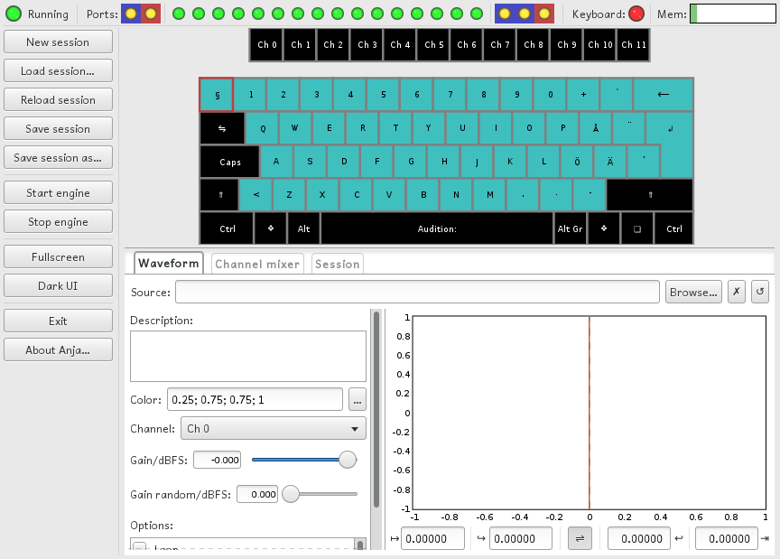
Figure 3.1: The Anja window, as shown after launching Anja without any command line arguments, and with a JACK server running.

Figure 3.2: The different parts of the Anja workspace. At the top, there is a status area showing the state of Anja. To the left is the action panel, used to control Anja's state. To the right is the keyboard view, which selects waveform slots and channels, and below that is the settings panel, which is used to load waveforms and control the playback of loaded waveforms.
The status area, shown larger in Figure 3.3, contains four parts as illustrated by Figure 3.4. The engine status and the keyboard status indicators should be self-explanatory: red  means that it is not ready, and green
  that it is ready. A similar convention holds for the port status area (see Appendix A for more details). In addition to being in the state of usable or not usable, ports are of different types: MIDI or Wave, input or output. MIDI ports have red-shaded background, while Wave ports have a blue-shaded background. Input ports are located to the left, and output ports are located to the right. Between the input and output sections, there are indicators with neutral or non-highlighted background. These represent the 16 internal Wave ports.

Figure 3.3: A detailed view of the status area. The status area contains four panels: An engine status indicator, port status indicators, a keyboard status indicator, and a memory usage indicator.

Figure 3.4: Layout description of the status area.
The memory usage indicator uses high-saturated colors for memory used by the current instance of Anja. The amount of memory used by other processes uses low-saturated colors. The level indicator is divided into two parts: RAM and swap. The RAM part is green, while the swap part is red.
To load a waveform, choose a slot by clicking on the corresponding key in the keyboard view (see Figure 3.2). It is possible to choose any typing key except system keys and the space bar. After choosing a key K, the corresponding key will be highlighted. Now click
If you want to remove the waveform from the slot, without loading a new one, click on
ffmpeg [14] and load the resulting files into different slots, mapped to different channels. Then use multi-channel output (see Section 3.7) and trigger playback of these slots simultaneously.
Before any sound can be heard from Anja, the following conditions has to be met:
As stated in Section 3.1, the state of the engine is showed by the leftmost panel in the status area. If a JACK server was already running when Anja was started, the engine should be running already. Otherwise, make sure that there is a JACK server running, and click the button New session.anja.
By default, Anja has two output ports: Master out and Audition. The difference between these ports is what sound that are routed to them. Master out is the main output, in the sense that all playback triggered by regular key input and MIDI (see Section 3.8) will be routed to this port. The Audition port is used for playback of the current slot (in Section 3.2 the slot mapped to key K), triggered by hitting Space. To stop all non-audition playback, hit Del. All auditions can be stopped by hitting Page Down.
Master out. This makes it possible to pre-listen to sounds without routing them to a PA system.
The connection status of Master out and Audition is shown by the two indicators with blue-shaded background in the output section of the port status area (see Figure 3.3 and Figure 3.4). When the engine is not running, these are black  . When the engine is running, a non-connected port is indicated by a yellow
  light, and a connected port is indicated by a green . For more details about port status indicators, see Appendix A.
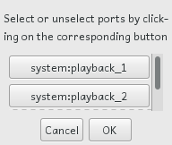
Figure 3.5: The port selection dialog. To route the signal to a port, toggle the corresponding button. The choices are confirmed by clicking
A port can be connected to other ports in the system by clicking on the corresponding status indicator. This brings up a dialog box that contains toggle buttons for all available ports (see Figure 3.5). Click
jack_connect [15]. To connect the mentioned ports to a pair of system playback ports. the commands would be
jack_connect 'New session.anja:Master out' \
    'system:playback_1'
jack_connect 'New session.anja:Audition' \
    'system:playback_2'
Catia [16]. In Catia ports can be connected using “Drag and drop”.Since the keyboard is shared between the playback triggering system and form input fields, playback can only be triggered from the keyboard when keyboard triggering is active. The keyboard status indicator (see Section 3.1) is red when a form input field has keyboard focus, and green when playback triggering is active. Keyboard triggering is activated by hitting Esc, or by clicking anywhere on the workspace that would not capture keyboard focus.
Similar to waveform playback (see Section 3.3), waveform capture requires that the audio engine is started. In order to capture a waveform, make sure that Wave in is connected to a signal source by clicking on the indicator for Wave in. That is, the leftmost indicator in the port status area (see Section 3.1). Then press Ctrl and the typing area key K that should be used for playing the captured waveform. If the Ctrl is released before the typing area key, playback of the recorded waveform is triggered. If K is released first, the capture process is stopped.
. Otherwise, it is red .
The playback behaviour and other properties can be controlled through the waveform tab in the settings panel (see Figure 3.2). An enlarged view of the waveform tab after loading a waveform file is shown in Figure 3.6. This view is activated by clicking on the corresponding key on the keyboard view.
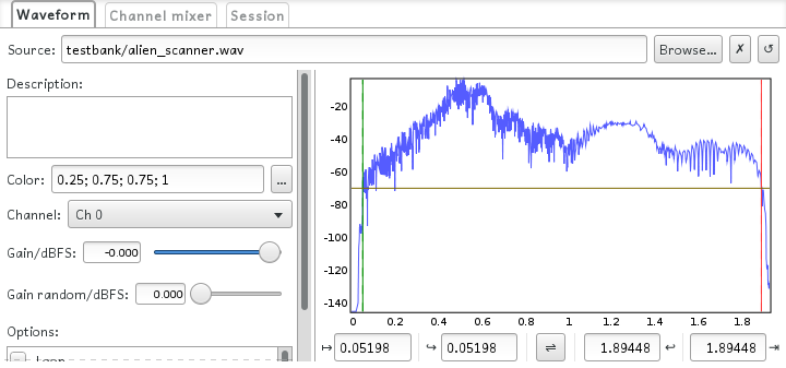
Figure 3.6: An enlarged view of the settings panel showing the waveform tab, after loading a waveform file. This tab contains various settings controlling playback of the selected slot.
The source file is chosen through the
It is possible to assign an arbitrary description to the waveform slot through the
It may happen that the description is long. Therefore it is possible to mark a key-phrase by surrounding it with square brackets. Then, only the text within the first pair of square brackets will appear at the virtual key. If there are no square brackets within the description, the first word will be used instead.
Like description (see Section 3.5.2), the ; (U+003b), where each component is in the range [0, 1]. If the
The
Before the signal reaches the strip for the selected playback channel (see Section 3.5.4), the signal is amplified by the given playback gain. The gain can be adjusted from -72 dB to 6 dB.
In addition to deterministic playback gain adjustment, it is possible to add a non-deterministic component to the playback gain. The parameter
There are different options for controlling the playback behavior. These are Loop, Sustain, Readonly, and Set gain on loop.
When Loop is enabled, playback will start form the loop begin cursor when the playback position reaches the loop end cursor, if no stopping event has occurred before that happens. For more information about adjusting cursors, see Section 3.5.8.
The Sustain flag controls whether or not a key release event should also send a stop event. When the Sustain flag is set, a stop event is not sent, emulating the effect of a pushed sustain pedal.
The Readonly flag controls whether or not it is possible to overwrite a loaded waveform with captured audio (see Section 3.4). Enabling Readonly prevents that a loaded waveform is accidentally overwritten by a record command.
As mentioned in Section 3.5.6, it is possible to only randomize gain on the trig event, but it is also possible set a new gain for each iteration in a loop. When this flag is set, the latter happens.
It may happen that only a part of a loaded waveform is interesting for playback or loop. With the trim panel (see Figure 3.7), it is possible to select the part of the waveform that should be played or looped. The graph shows in dBFS, the root mean square signal power integrated over 1 ms, as a function of time in seconds. On top of the function graph, there are four cursors showing playback and loop range, as well as the auto-trigger threshold level. In addition to the plot window, there are four input fields that can be used to set playback cursor positions by entering the corresponding time position in seconds. The leftmost input field
Figure 3.7: The trim panel. Together with cursor positions, the plot window shows in dBFS, the root mean square signal power integrated over 1 ms as a function of time in seconds. Below the plot window there are four input fields that sets the positions of the playback cursors.

Figure 3.8: The playback sequence. Playback starts at the begin cursor and passes the loop begin cursor. When the playback position reaches the loop end cursor, and loop is activated and the engine has not received a stop message, the playback will continue from loop begin when it reaches loop end. Otherwise, playback continues until end is reached, or a stop message is received.
Before going into the details on how to set playback and loop ranges, it is good to get an overview of the playback sequence illustrated in Figure 3.8. Playback starts at the begin cursor and passes the loop begin cursor. When the playback position reaches the loop end cursor, and loop is activated and the engine has not received a stop message, the playback will continue from loop begin when it reaches loop end. Otherwise, playback continues until end is reached, or a stop message is received.
The primary way of setting the position of a cursor is to drag the cursor into position. The position of the begin is controlled by the green solid cursor and the position of the loop begin is controlled by the green dashed cursor. The end cursors are drawn the same way but in red instead of green.
Another way of adjusting the cursor positions is to drag the auto-triggering cursor while pressing Shift. This will move the begin and end cursors to the first or last position where the signal power exceeds the current threshold level. If this requires that the loop cursors to move, they will be pushed by the non-loop cursors.
A third option is to enter cursors positions into the input fields below the plot window. The leftmost input field
Reversed playback is toggled by the middle button in the trim panel (see Figure 3.7). What it does is to swap the direction shown in Figure 3.8 by reversing the list of cursor. Another way of enabling reversed playback is to manually position the end cursors before the begin cursors. When begin and end cursors meats, the reverse toggle button changes state.
The Channel mixer is shown in Figure 3.9. The Channel mixer controls the playback volume for the different playback channels. To the right of all channel strips, there is a master gain control, which controls the playback volume of the mixed channels. In addition to a gain control, each channel strip also contains an input field for selecting a channel color, which works similar to the color input field for waveforms (see Section 3.5.3), and a control for determining the duration of automatic fade-in/out operations.
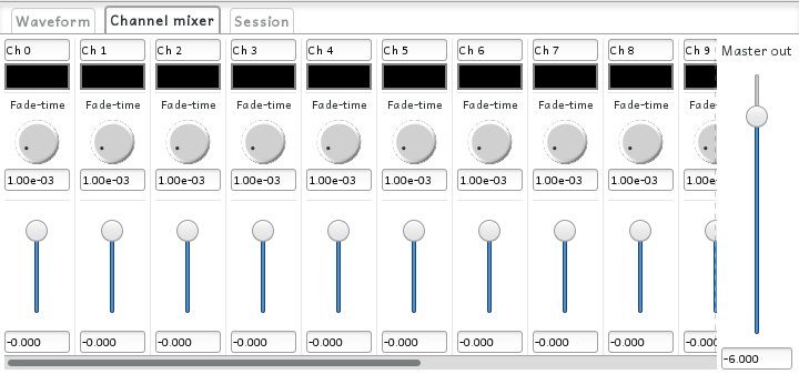
Figure 3.9: The Channel mixer. Each channel strip has a label, a color, a fade time knob, and a volume slider. To the right of all strips, there is a master gain control, that affects the gain of the mix.
Automatic fade-in/out is triggered by hitting Fk while pressing ↑/↓, where k is the channel number. After fade-out, the channel is muted until it is unmuted or a fade-in occures. Mute and unmuting a channel is done by hitting the corresponding channel key (Fk) while pressing ← or → respectively.
When a channel is muted and the engine uses single-channel output, the corresponding indicator in the port status area (see Section 3.1), is red . The same is true when the engine uses multi-channel output (see Section 3.7). In the case the engine uses multi-channel output and the corresponding port is not connected, the muted state is indicated by a black indicator. Unmuting the channel, reverts the corresponding indicator to its original state. All possible states of the port status indicators are listed in Appendix A.
Anja has the option to use individual channel output. This enables the use of external effect processors on the different channels. To activate this feature, check the checkbox Master out and Audition. These ports are connected in a similar way as described in Section 3.3.2, that is by clicking on the corresponding status indicator (see Section 3.1).
The signal sent to the channel-dedicated output ports are taken after the channel strip, but before the master gain adjustment. When activating multi-channel output, the port status indicators for the playback channels turns yellow or black (depending on mute state) since the corresponding ports are not connected to any input port. However, the signal is still being routed to Master out. For a complete overview of the signal flow, see Appendix D.
Non Mixer [17] can be usedMIDI is a standard for communications between musical instruments, and other equipment [18]. Through MIDI, Anja can be controlled by other MIDI enabled devices or software applications. To make it work, connect the MIDI in port to any MIDI output port such as midi_capture_1, and Anja will respond to external MIDI messages. Implementation details of different MIDI messages can be found in Appendix E.
Anja can also be used to control other MIDI enabled devices or software applications. To let Anja do so, connect MIDI out to a suitable MIDI input port on the device or software application you want to control. Anja posts the messages generated by the computer keyboard to MIDI out. The messages generated in different situations are listed in Appendix E.
MIDI out is connected to a MIDI input port, Anja resets the state of the receiver, and updates its channel volumes. This means that if the owner of the input port plays any note, there will be no more audio output from that device or software application until the next “note on” message comes.
The session tab, shown in Figure 3.10, contains some session-wide settings. The
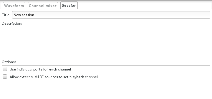
Figure 3.10: The session tab. From this tab, it is possible to give the session a title and a description, as well as enabling multi-channel output (see Section 3.7).
[2] https://daringfireball.net/projects/markdown
[3] http://doom.wikia.com/wiki/Doom_file_template
[4] http://www.mega-nerd.com/libsndfile
[5] http://www.mega-nerd.com/SRC
[7] https://wiki.gnome.org/Projects/GtkSourceView
[8] http://www.hydrogen-music.org/hcms
[9] https://github.com/milasudril/anja/releases/latest
[10] https://github.com/milasudril/maike
[11] https://www.gnu.org/software/wget/
[12] https://stedolan.github.io/jq/
[15]
jack_connect manual page
[16] http://kxstudio.linuxaudio.org
[17] http://non.tuxfamily.org/wiki/Non%20Mixer
[18] http://midi.org
This table shows all states the port status indicators can have.
| Indicator | Meaning |
| Engine is not running |
| Channel is muted, and not connected to any port |
| Channel is unmuted and not connected to any port |
| Channel muted, and connected to some port |
| Channel unmuted and connected to some port |
Anja uses libsndfile in order to load waveform files. Thus the file formats supported by Anja, are the same as those supported by libsndfile. If libsndfile does not support the file format of a particular waveform file, it can probably be converted to a supported file format by using ffmpeg. In such case, remember that you should not transcode to a lossy format (mp3 to ogg is bad), but rather to a lossless format (mp3 to wav is good).
These are the key bindins used in Anja. Notice that any of these except Esc requires that the computer keyboard is active.
| Key combination | Function |
| Ctrl+key | Record to key |
| Esc | Activate the computer keyboard. Hit this key if other keys in this list have no effect. |
| Del | Stop all audio playback on Master out or channel ports |
| key | Start playback of the slot associated with key |
| Page Down | Stop all audio playback on Audition |
| Space | Start audition playback of current slot |
| ↑ + Fk | Fade in channel k |
| ↓ + Fk | Fade out channel k |
| ← + Fk | Mute channel k |
| → + Fk | Unmute channel k |
The following graph illustrates the signal flow of Anja.

The following table lists all MIDI messages that Anja processes, and how they are processed.
| Message | Control code | Anja's response |
| NOTE_OFF | N/A | Stop all playback that is associated with the given key |
| NOTE_ON | N/A | If possible, start playback using the slot given by the first data byte. If channel override is allowed (see Section 3.8), the mapped waveform will be played through the channel given by the message. Otherwise, the it is played through the channel set by anja (see Section 3.5.4). |
| CONTROL_CHANGE | CHANNEL_VOLUME | Set playback channel volume. Notice that Anja assumes that the value is a linearly mapped dB value (0 corresponds to -72 dB, 127 corresponds to 6 dB), as opposed to General MIDI, which says that the value should be a regular gain. The reason for this implementation is to make better use of the seven bits available in a single channel volume message. |
| SOUND_OFF | Stop all ongoing playback. If The last data byte is non-zero, it stops all Audiotion playback. Otherwise, all other playback is stopped. | |
| GENERAL_PURPOSE_1 | Start a fade-out on the given channel. The second data byte controls the decay rate. | |
| GENERAL_PURPOSE_2 | Start a fade-in on the given channel. The second data byte controls the decay rate. | |
| GENERAL_PURPOSE_3 | If possible, enable recording to the slot given by the second data byte. If recording is already enabled, the last block of the current recording is discarded. | |
| GENERAL_PURPOSE_4 | If possible, disable recording to the slot given by the second data byte |
This is a summary of all command line options. Values inside square brackets are optional. The different argument types accepted by the different options are
bool := (true | false | yes | no)
can be true, false, yes, or no. true is equivalent to yes and false is equivalent to no. It is also possible to use a number. In this case, any non-zero value is true and zero is false.
filename in := (A name of an existing file)
If there is no file with the given name, an error occurs.
filename out := (A valid filename)
If a file with the same name already exists, it will be overwritten.
theme := (dark | light)
window mode := (fullscreen | windowed)
--about[=filename out]
prints an about message to filename out. Without argument, the data is written to standard outout.
--help[=filename out]
prints all availible command line options to filename out. Without argument, the data is written to standard outout.
--version[=filename out]
prints version information to filename out. Without argument, the data is written to standard outout.
--theme=theme
selects the UI theme. The default theme is dark. Notice that theme modes does not work on all GTK+3 themes. In this case, this option has no effect.
--window-mode=window mode
selects the window mode. The default mode is windowed.
--session=filename in
loads a saved session from filename in. Notice that this option is ignored if script is given.
--script[=filename in]
reads and executes commands from filename in. Without argument, the session is read from standard input. The command stream works independently of the UI. Notice that this option overrides the session option.
--offline=bool
determines whether or not Anja should be started in offline mode. By default, Anja tries to connect to the JACK server determined by the JACK_DEFAULT_SERVER environment variable. This option can be used to override that behaviour.
Anja session files are plain text files, that contains all session properties, waveform settings, and channel settings. Session files do not contain any waveforms. Instead they refer to the file that contains the actual waveform. The idea is that the session file acts as a machine-readable README file, that is somehow bundled with the waveform files. Thus, the session file should be very easy to read by humans.
For an example of what a session file might look like, see testbank/testbank.txt in the source repository. The file is organized as a hierarchical key-value store. Section headers begin with a number of consecutive # (U+0023), which have to appear as the first non-whitespace character on a line. The header ends with a newline character. The section level is the same as the number of characters used to begin the header. A key begins with a ~ (U+007e), which similarly to the section header delimiter, has to be the first non-whitespace character on the line, and ends with : (U+003a) or a newline character. After the ending delimiter, follows the associated value. At any point, a \ (U+005c) can be used if a delimiter should be processed literally.
In general, any character that has no particular meaning in the current context, can be used without escaping. To make it possible to write session files in a more readable way, some special rules apply to whitespaces. Whitespaces immediatly following a delimiter or another whitespace, are ignored. As mentioned above, newline characters cannot appear unescaped in keys. In values, two or more newline characters that are only separated by other whitespace characters, are collapsed into two newline characters. Unescaped single newlines are treated in the same way as any whitespace.
If the first key in a section is Description, it is possible to ommit the key, and write its value right after the section header. This makes it possible to write session files more like a regular document.
This chapter lists all external dependencies, as extracted by maike, used within the Anja project. The items listed in Section H.1 are also needed to run Anja. On some distributions, library packages are split into a runtime package and a development package. In this case, only the runtime package is needed to run Anja, but the development package is needed to compile Anja.
The following list contains all libraries except for the C++ runtime library, required by Anja.
The following list contains all tools, required to compile Anja.
The following list contains all external resources, required to compile Anja. This list includes static resources like fonts, and packages for scripting languages.
With the --script option (see Appendix F), it is possible to perform some tasks when starting Anja. This option has been added to make it possible to generate relevant screenshots for this manual. This means that only features that are needed for that purpose are currently implemented. Also, the syntax may change in a future release and it is not very tolerant with respect to whitespace. Nevertheless, this appendix contains a list of all implemented commands.
layout inspect
prints coordinates of bounding boxes for various parts of the GUI to standard output. The outline in Figure 3.2 has been generated by using this command.
port selector open,port indicator index
opens the port selector dialog (see Figure 3.5) as if the user clicked on the port status indicator in the status area (see Section 3.1), with the given index
port selector close
closes any open port selector dialog
waveform load,slot,filename in
Loads filename in into slot, where slot is an integer in [0, 128[
session load,filename in
Loads the session filename in
settings,tab
Reveals tab, where tab is one of waveform, channels and session
The source code of Anja is divided into three major components: Engine, Session data storage, and UI. The engine is the component that communicates with JACK. The session data component is responsible for disk I/O of session and waveform files. The UI code handles the user interface. In addition to these components, there are in the repository, some more general classes, MIDI interaction helper files, resource files, test data, and also the source files for this manual. These file categories are represented by a directory, which contains all of its files.
The component interaction is illustrated in Figure J.1. It is the engine and the UI that are the “active” components. When a setting is changed, the UI will modify the corresponding field in the session data. If that change should affect another part of the UI, the UI will update the relevant parts itself. When the engine needs a waveform and its parameter values, it will fetch these from the session data component. This direct approach makes the code easier to follow and keeps the session data component clean, but requires changes at more places in the code, compared to an orthodox MVC approach, where the model updates all registered views upon a succeeded change request.

Figure J.1: Component interaction in Anja. The engine and the UI are the active components, while the session data component acts as a passive data store.
When the user triggers the engine, the UI posts a MIDI message, by calling Engine::messagePost, to a ringbuffer, which is read by the realtime thread in the engine. The messages are then processed by the engine. Some actions requires that the engine updates the UI. This problem is solved by another FIFO with two post methods: UiContext::messagePost and UiContext::messagePostTry. The former will block until the message can be processed, while the latter will simply fail if the message cannot be processed. Thus, from any realtime context, the latter must be used.
Some requests to the session data component may take a longer time. In this case it is possible to pass a progress callback object to the affected method. Typically, the callback object will be some of the UI objects, but there is no explicit association from the session data component to the UI component.
The UI component has been designed to hide as much as possible about the underlying framework, while trying to preserve the native look and feel. This means that no widget exposes the internal handle, and most of the common UI widgets, i.e. buttons, checkboxes, comboboxes, labels, sliders, and text input fields, are nothing more than thin wrappers on top of the framework. Also, the file selection dialog belongs to this category. Widgets that have a sematic difference between different platforms, are emulated using these basic widgets. As an example, listboxes are emulated using a ButtonList, which itself consists of a set of buttons. Some widgets such as the XYPlot are completely missing from common UI frameworks. In this case, they have been implemented directly at top of the framework. This is because it is hard to construct a general abstraction on top of a drawing API.
In addition to widgets, there are “containers”. A container is any class that implements the Container interface. Since some frameworks, such as the classic Windows API, is easiest to work with if the container is created before its children, and this design is more restrictive than creating the widgets before the container, Anja uses the container-first priciple. Notice that unlike in GTK+-3.0, containers are not widgets. In fact, there is no exposed Widget base class, since the only polymorphic behaviour required by widgets, positioning, are handled by the framework.
Event handlers are registered by passing a callback object and an id, to the widget of interest. Different widget has different requirement of the callback object. More information about this topic can be found in the include file for the widget.
Modal dialog boxes are emulated as modeless dialogues that disables the main window. The Dialog is a template that owns a widget, and some buttons specified by a dialog trait. Event handlers for the buttons are handled in a similar way as for widgets. A callback object is assigned to the dialog, and when the user activates a button, the corresponding method on the callback object is invoked.